At some point I accidentally spotted an extra button next to the parking brake button in a picture.
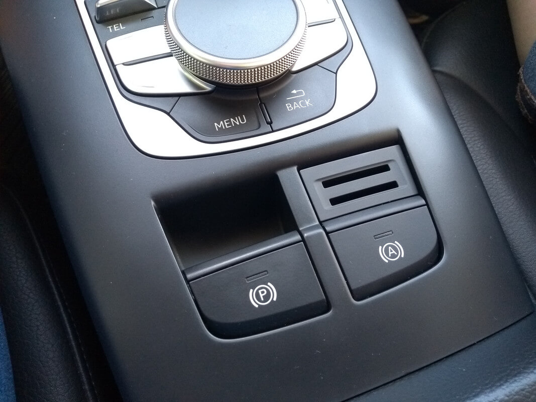
After googling it, I found out it’s the Auto Hold button — it holds the brake pedal engaged when you come to a complete stop somewhere, for example at a traffic light. In the US this feature was never fitted on the Audi A3 8V; it’s usually fitted on the European-spec car — I guess Europe has more hills and traffic lights.
I wanted to add this button and the feature it enables. I ordered a ready-made kit on AliExpress for the facelift version (white backlight) for $90:
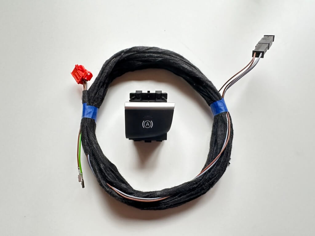
And when I was already about to install the button, I found out the old coin tray doesn’t fit — you need a special one for the Auto Hold button. Finding just the coin tray on its own is very hard: in our country Audi A3s at the salvage yards are mostly US-spec, and as I mentioned above, this button (and the matching coin tray) was never fitted on those. I opened ETKA, looked up the part number and ordered it from the factory for $10.
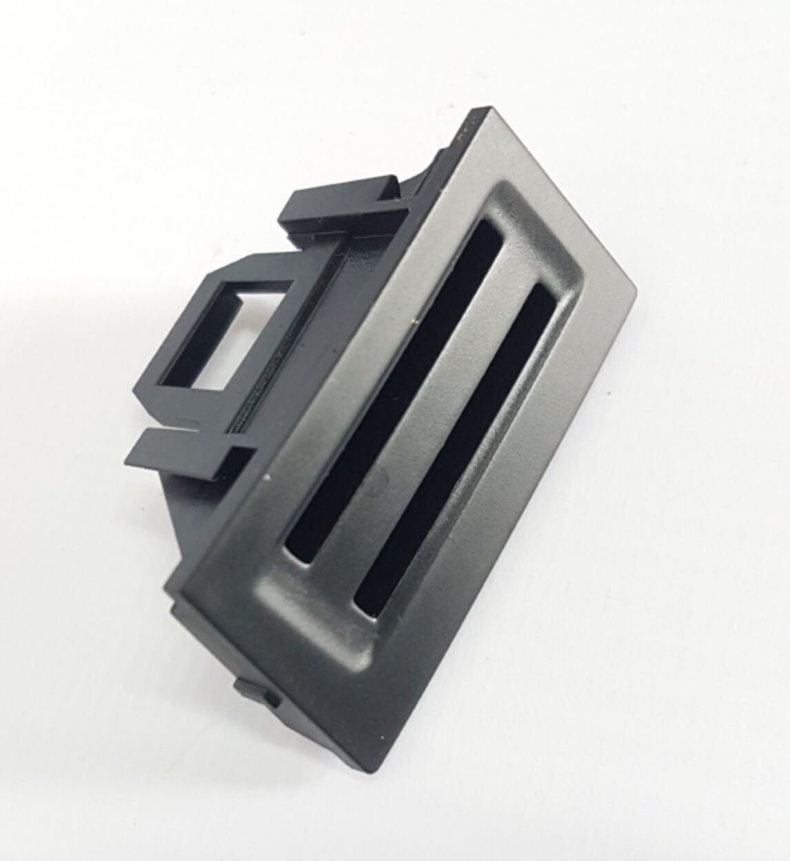
In the end, these are the parts needed for the retrofit, for a left-hand-drive car:
- 8V1927143C – Autohold button with chrome trim (8V1927143B – without chrome)
- 8V1858323B – coin tray
- 0.35 wiring
- special pins (terminals) for the ABS connector
For the install you’ll need to take apart the fuse box area, the center console and the glovebox. But first, be sure to disconnect the battery terminal.
I started with the center console. To remove it, first you need to lift the shift knob trim upward — this is simple, just pry it with trim tools and pull the trim itself up, then remove the gear position indicator, which also comes off by pulling it up.
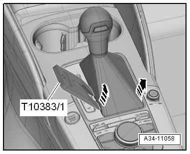
Then the console itself — insert trim tools on the sides and pull up. Lift it and pull it through the openings in the shifter trim, then it’s just a matter of disconnecting the connectors.
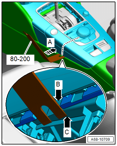
We pull out the coin tray and insert our new button-with-coin-tray in its place.
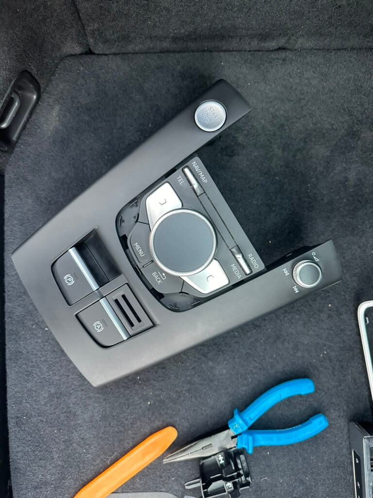
Next comes the moment when you need to start connecting and routing the wires — for that we’ll need the wiring diagram.
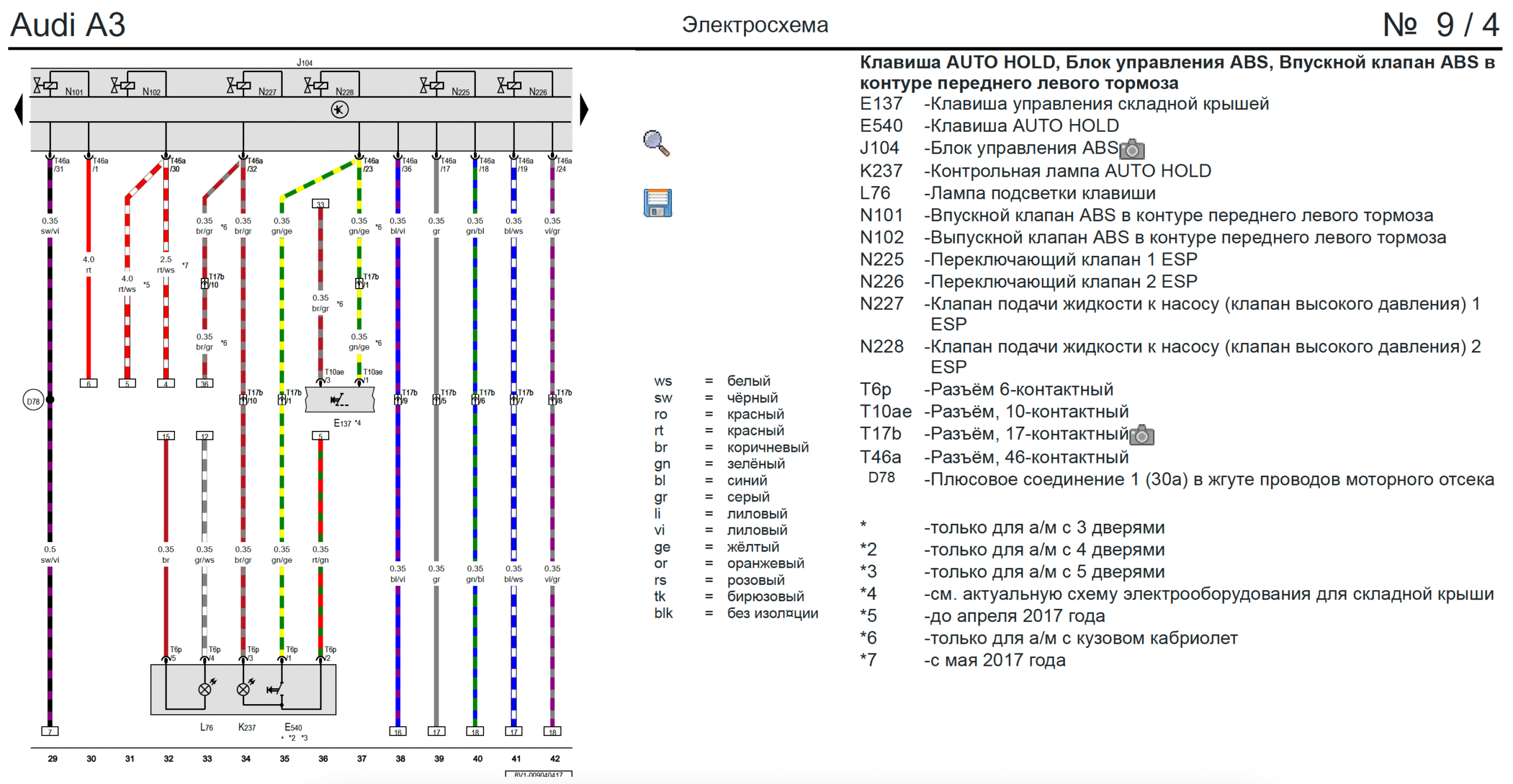
From the diagram we can see the button has a 6-pin connector, of which 5 pins are used. The guy in China who bundled the wiring for the button seems to be a bit colorblind — half the wire colors don’t match up.
The first thing to do is tap into the parking brake button’s wiring — we need ground (brown) and backlight (white-gray).
| Auto Hold button | → | Parking brake button | Color | Description |
| PIN 5 | → | PIN 6 | Brown | Ground |
| PIN 4 | → | PIN 5 | White/gray | Button backlight |
Next we’re left with three unused wires — one goes to the fuse box, and two wires go to the ABS unit under the hood.
| Auto Hold button | → | Destination | Color | Description |
| PIN 2 | → | Fuse box, fuse 33 | Red/green | Power |
| PIN 3 | → | ABS unit, PIN 32 | Brown/gray | Button lamp |
| PIN 1 | → | ABS unit, PIN 23 | Yellow/green | Signal |
Carefully, without removing the trim, I ran the wiring to the fuse box — this is quite doable. The center console can be put back together.
Next you need to remove the trim under the steering wheel to get access to the fuse box.
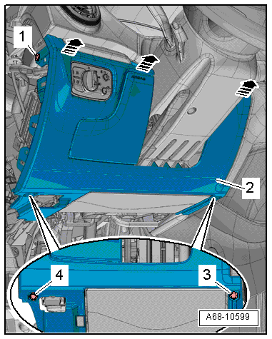
Then you need to pull out the fuse box — it won’t come out far, but that gives you enough room to feed the power wire in from behind into fuse slot 28. After that, put everything back together in reverse order.
To route the wires under the hood to the ABS unit, you need to remove the MIB unit with special tools, plus the glovebox itself, disconnecting the connectors for the lighting, airbag, etc. along the way.
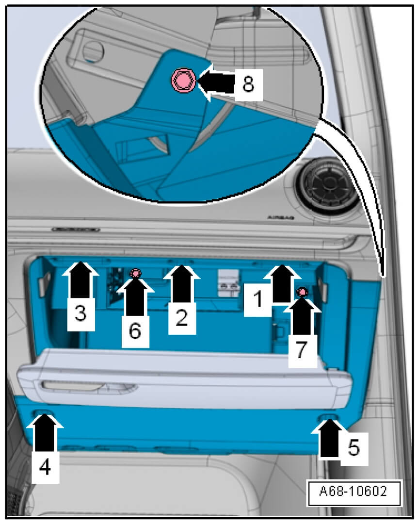
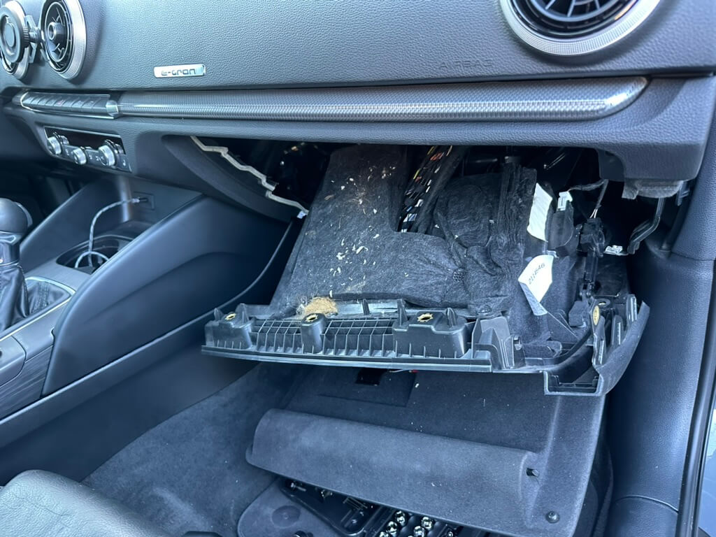
Now, in the footwell, under the trim, you need to feel out the rubber grommet and carefully pierce it. Feed two wires through it, catch them on the under-hood side and route them to the ABS unit. The glovebox can be put back together.
Now for the work under the hood. Remove the cover from the ABS unit.
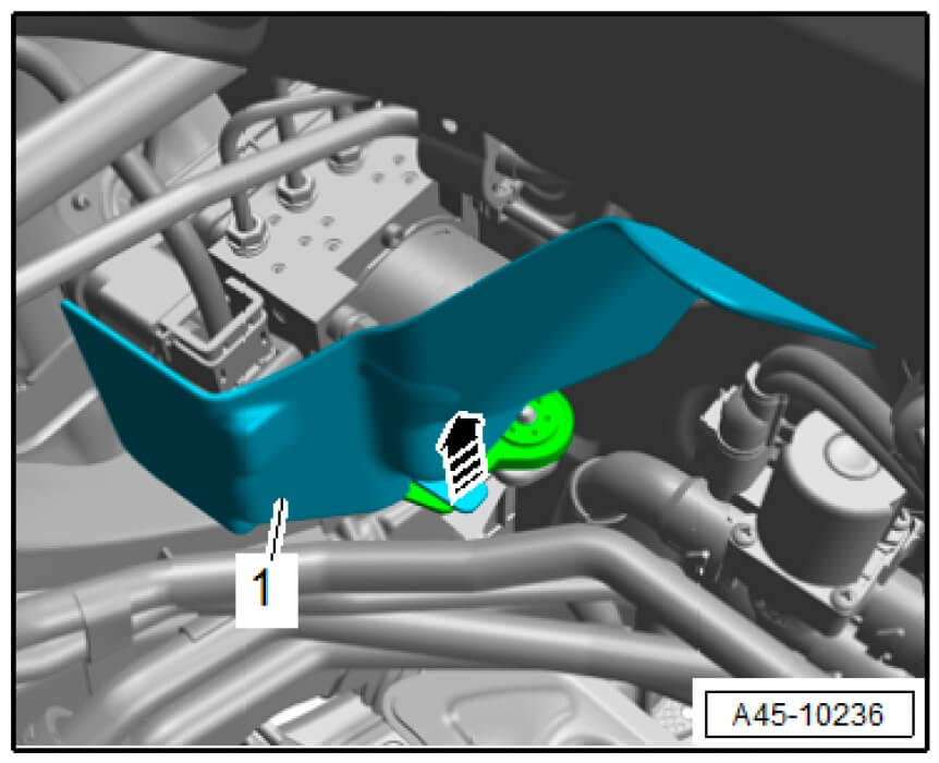
And pull out the connector
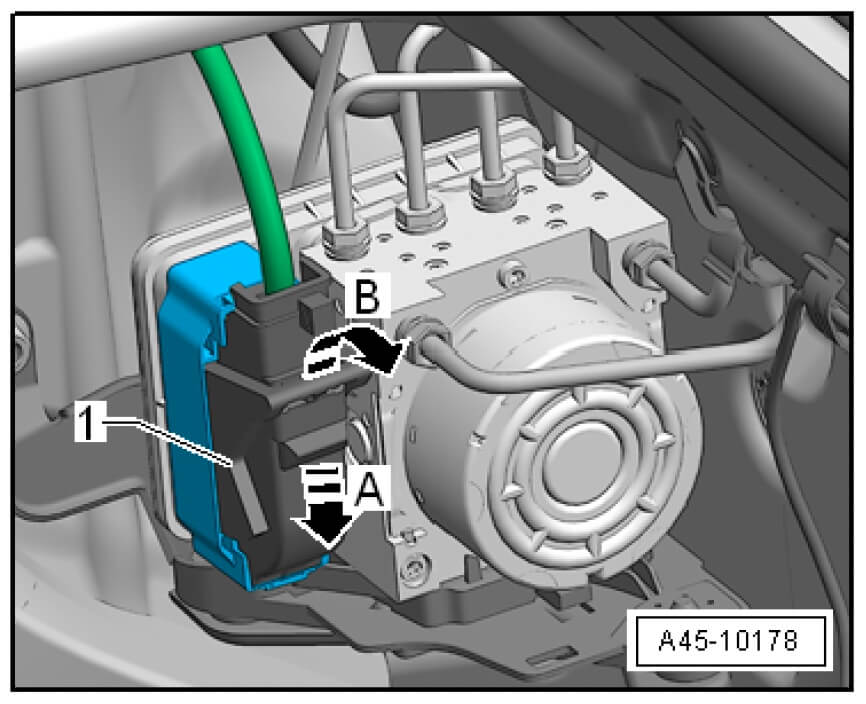
Now the connector needs to be pinned, but here’s where I got caught out — the guy in China had used ordinary pins, and it needs the special ones made for ABS. At this point I set aside pinning this connector and ordered the correct pins. A couple of days later and I had them.
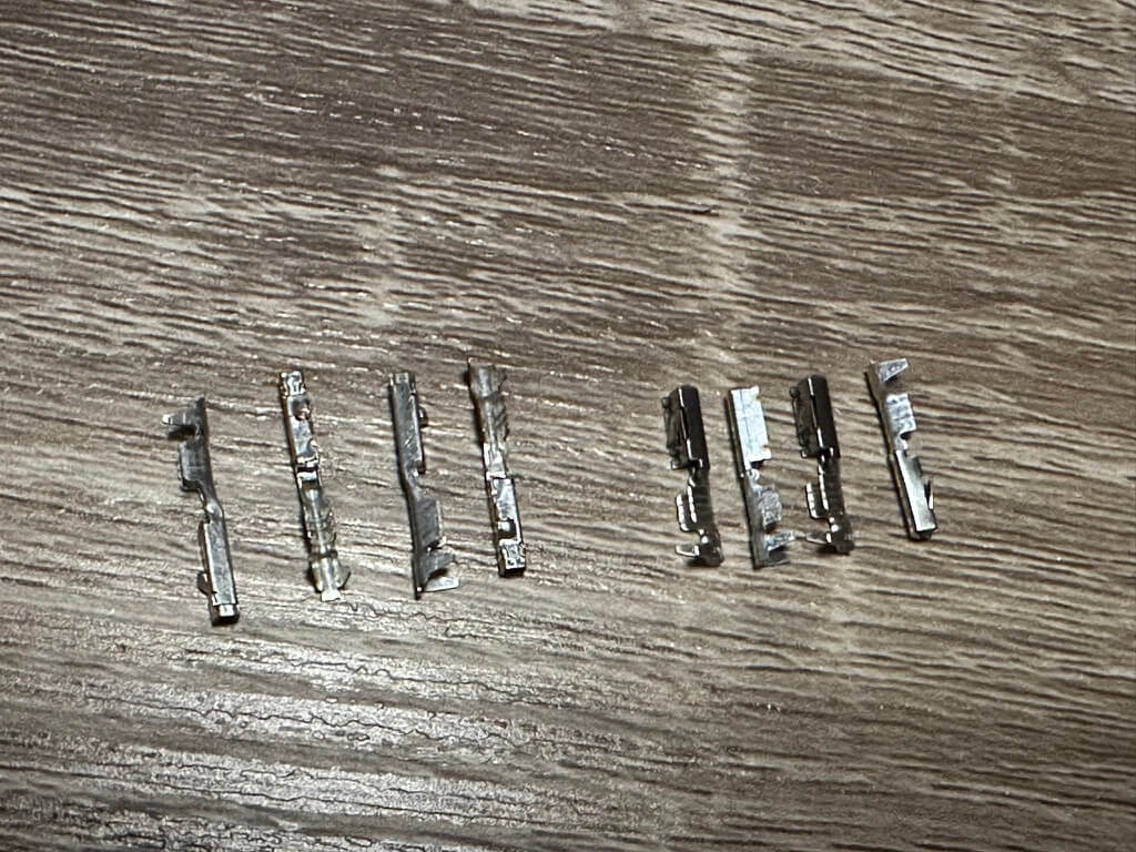
Now I could continue. I cut off the old pins, stripped the wire with a stripper and crimped on the new pins. On the side of the connector there’s a small pink tab that acts as a lock — you need to press it in, which lets you insert the pin into the connector; after inserting, close the lock again. I pinned pins 23 and 32 according to the table I gave above.
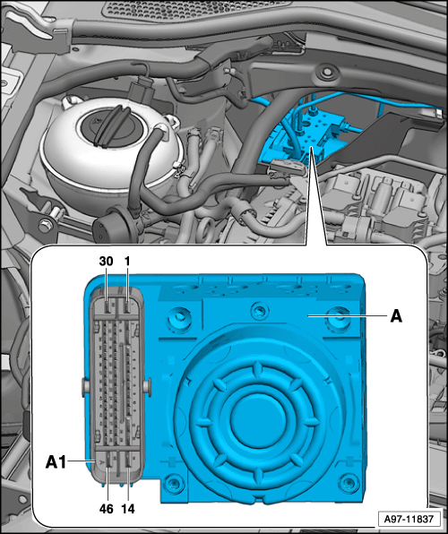
Put everything back together in reverse order.
Now all that’s left is coding the 03 ABS control unit. The correct coding depends on the specific ABS unit. Mine has HW: 5Q0614517AH, and the following coding was applied to it:
03 ABS
Long coding
-
Byte 8
- Bit 1 Autohold indicator in cluster
- Byte 19 Mirrors Byte 8
-
Byte 23
- Bit 0 Autohold enabled
-
Byte 28
- Bit 2 Autohold turn on message // optional
The overall coding string was this:
Long coding
- 12FF409238242272897C0A0881CA2948021C44915081947238A15056828802
And became this:
Long coding
- 12FF4092382422728B7C0A0881CA2948021C44D15081947338A15056868802
For information on what each coding value means and how to code a different ABS unit, there’s this table.
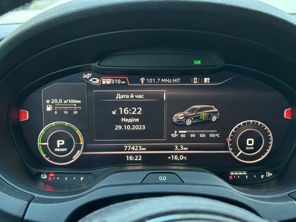
Now let’s check that it works. For Auto Hold to work, you need to start the engine and be sure to buckle your seatbelt. Turn on the Auto Hold button — it should light up and indicate it’s active — and start driving; then come to a full stop somewhere and take your foot off the brake pedal, and the car should stay in place. On my instrument cluster, a green PARK icon lights up at that moment; then a light press on the gas and the car continues moving.
That’s it for now. In the next article I’ll cover retrofitting the tire pressure monitoring system.